Correction to the video!!! +12V DC is taken from the third pin from left on the userport output and connected to DC to DC step down voltage regulator.

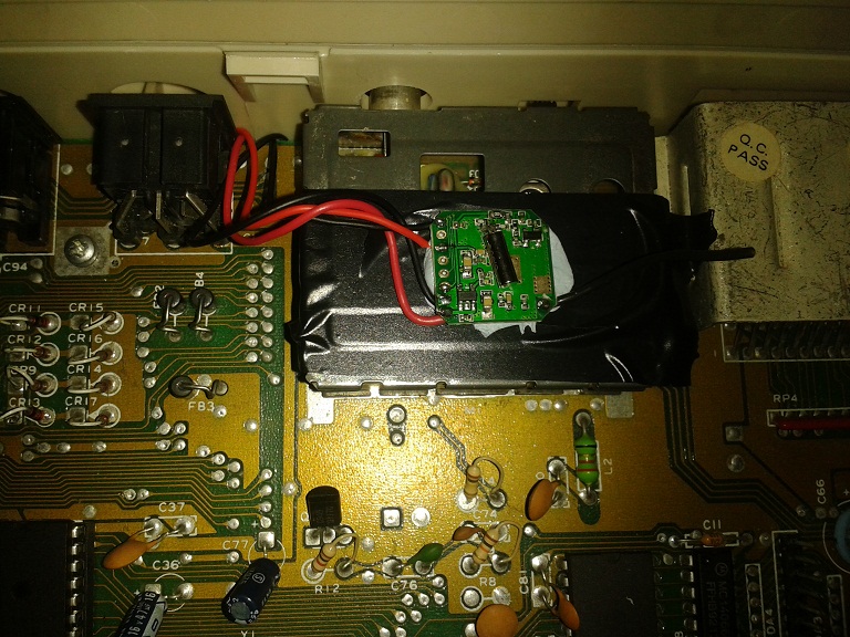
This is how it looks like once it's finished.

First thing you have to do for this project is disconnecting one of the legs of the resistor at the R19.
This is very important as it overheats when we are running on DC only.
Remove the fuse as it's useless and also if you plug in the regular power supply by accident,removed fuse will save your C64C.

I salvaged 6 Li-ion 18650 batteries from an old laptop battery pack.I recharged them using a li-ion charger and made sure they are all at close capacity before making a 3S pack.
This is the battery protection board that I used for this project.

Other side of the board.

That is where I soldered the +12V out from the battery pack.

Also (-) from the battery pack soldered to ground.

We also need 5V to run our C64.For this I used a
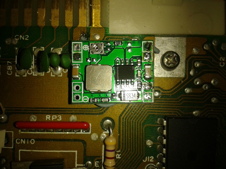
Step Down Voltage Regulator.As it is adjustable,you need to set it to 5V before connecting it to your C64 board.

In the image above,you can see how I connected the voltage regulator to the board.

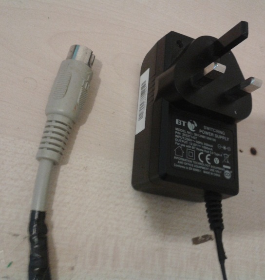
I used an old router power supply for this project.It provides 12V at 1A.
It can charge the battery pack in about 1,5 hours and gives me up to 2 hours play time.
If you want to charge while using your C64,you should get an at least 1.5A rated power supply.

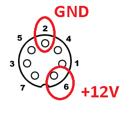
This is the diagram,how you need to wire up the power connector.

This is the 2.4Ghz AV transmitter module.If you want to buy a ready made one,follow
this link.For the TOD clock signal generator,take a look at
Pasi Lassila's Blog Entry.I ordered a
NE555 Adjustable Module for the TOD generator.Once I recieved it,I will update this tutorial.
Check out
this video.